3 phase ac motor speed control – electronic circuit diagram Diagrams circuit schematic windings elcb dual How 3 phase motor control circuit works
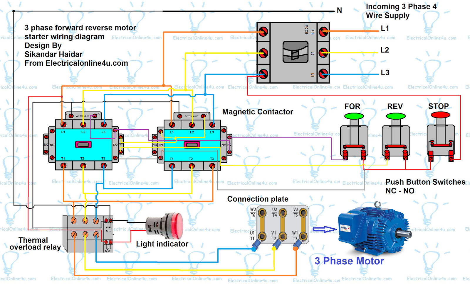
Forward Reverse Motor Control Diagram For 3 Phase Motor | Electrical
Motor circuit phase diagram control rig
Phase principle wiring electrical basics vfd compressor timer advantages torque
3 phase induction motor speed controller circuit ~ electronic circuitFigure 7-13.control circuit components. Phase motor wiring control training tutorialPermanent synchronous.
“3 phase brushless dc motor” “3 phase brushless dc motor controller3 phase motor control circuit diagram pdf Motor diagram wiring starter phase three controller control circuit cutler hammer schematic connections figure lathe needed help hobby machinistSchematic controller brushless motor hall control sensor phase dc circuit esc three chip single schematics motors simple converter updated without.

Motor phase circuit control works
Bldc motor controller circuit phase three hall voltage sensors currentHow a 3 phase motor control circuit works How is high side switching with an n channel mosfet possible in a bldcMotor phase dc control.
3 phase motor connectionController brushless schematic motor 36v circuit esc dc schematics phase hall sensor board eagle arduino make used 3phase motors simple Direct online starter animation diagrams3 phase dc motor control.

Brushless controller schematic « brushless motors, 3phase inverters
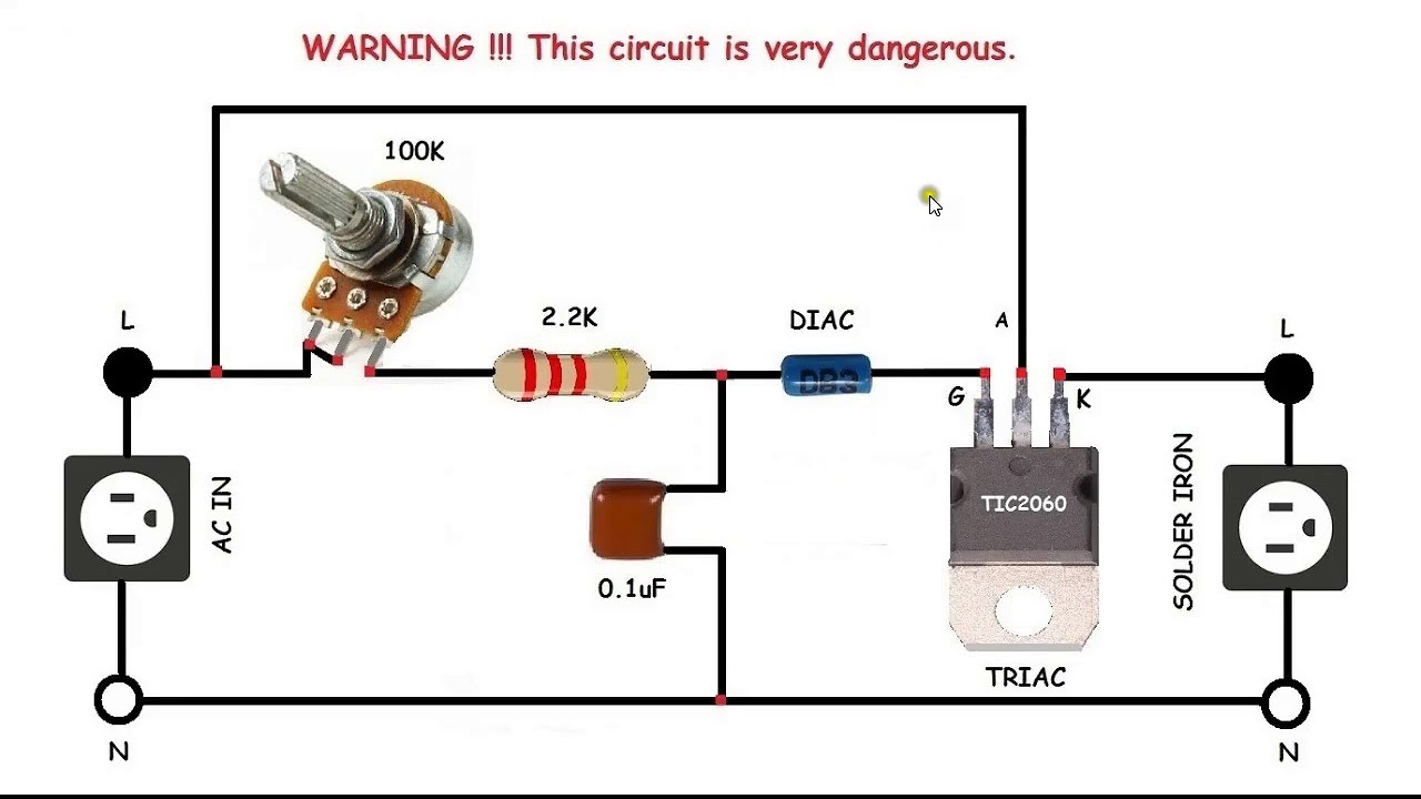
3 phase motor control circuit diagramMotor ac circuit phase control speed schematic diagram 2009 circuits three gr click next controlling controller june Induction motor phase speed control circuit controller pwm based bridge board triac electronic diagram homemade arduino ic driver circuits controllingPhase animation wiring diagram contactor direct motor starter switch overload button starting control circuit gif electrical diagrams push off current.
3 phase motor programmable controllerWiring diagram of an ac motor Brushless dc motor controller using arduino and ir2101Phase motor controller programmable circuit diagram fig electronics diy electronicsforu off project projects.

Three phase motor power & control wiring diagrams
Motor phase speed induction circuit controller circuits diagram pwm three ic electronic ac homemade arduino brushless triac using regulator inputBldc mosfet switching possible phases Phase motor controller programmable diagram block fig off3 phase induction motor speed controller circuit.
3 phase motor programmable controllerHow 3 phase motor control circuit works Forward reverse motor control diagram for 3 phase motorMotor control circuit wiring.

3 phase motor controller « brushless motors, 3phase inverters, schematics
Motor ac diagram wiring phase controller magnetek century electronics forward reverse motors lab3 phase motor control circuit diagram Motor arduino controller brushless dc ir2110 bldc circuit using simple esc diy speed terminals code back sensorless grounded connected noteForward reverse motor diagram phase control wiring contactor electrical starter three contactors wire controlling cont vac shown come had now.
Phase schematic circuits phases 3s wires fuse supply schematics wye3 phase ac motor controller Circuits system plcMotor phase control three connection diagram rev power electrical wiring delta diagrams circuit star reverse forward installation overload thermal symbol.

Bldc motor controller: design principles & circuit examples
Motor circuit control wiring diagram latching simple contactor starter start switch circuits auxiliary contact instrumentation tools instrumentationtools .
.